JFET Current Source: Derivation & Preselection
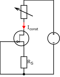
Current source using an N-channel JFET
1. The Shockley Equation
The basis for calculating a current source with a JFET is the Shockley equation for the saturation region:
\[ I_D = I_{DSS} \cdot \left(1 - \frac{V_{GS}}{V_{GS(off)}}\right)^2 \]
To find the required source resistor \( R_S \), we rearrange the equation for \( V_{GS} \):
\[ V_{GS} = V_{GS(off)} \cdot \left(1 - \sqrt{\frac{I_D}{I_{DSS}}}\right) \]
The resistance is then calculated using Ohm's Law at the source pin:
\[ R_S = \frac{|V_{GS}|}{I_D} \]
2. Physical Derivation
The Shockley equation describes the JFET in the saturation region. The quadratic characteristic results from the geometry of the space charge region (SCR):
- Control: A negative voltage \(V_{GS}\) expands the SCR at the gate-channel junction.
- Channel Cross-section: The effective width \(w\) of the conducting channel decreases. Since the expansion of the SCR is proportional to the square root of the voltage (\(x \propto \sqrt{V}\)), the conductance of the channel changes.
- Integration: By considering the charge transport over the entire channel length \(L\) and accounting for the fact that the channel is "pinched off" when reaching \(V_{GS(off)}\), the integration of the charge density results in the parabolic shape:
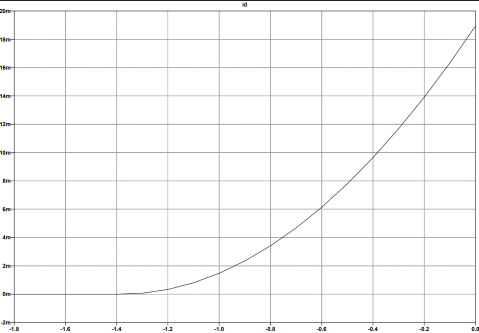
Characteristics of the LTspice Model J113 N-Channel JFET
3. Parameters from the LTspice Model
In your J113 model
.model J113 NJF(Beta=9.109m Betatce=-0.5 Vto=-1.382 Vtotc=-2.5m Lambda=8m Is=205.2f Xti=3 Isr=1988f Nr=2 Alpha=20.98u N=1 Rd=1 Rs=1 Cgd=6.46p Cgs=5.74p Fc=0.5 Vk=123.7 M=407m Pb=1 Kf=12300f Af=1 Mfg=Linear_Systems)
the values are:
- \( V_{GS(off)} \) =
Vto= \(-1.382 \, \text{V}\) - \( I_{DSS} = \text{Beta} \cdot Vto^2 = 9.109\text{m} \cdot (-1.382)^2 \approx 17.4 \, \text{mA}\)
In an LTspice model for a JFET (NJF), the parameters of the classic Shockley equation are mainly determined by Beta and Vto. Here is the mapping:
1. Main Parameters
Vto(Threshold Voltage): Directly corresponds to the pinch-off voltage \( (V_{GS(off)} )\). In your model, \( V_{GS(off)} = -1.382\text{ V} \).Beta(Transconductance Parameter): This is the scaling factor for the current. It is directly related to the maximum current \(I_{DSS}\).
2. Relation to the Shockley Equation
LTspice uses a slightly different form of the equation internally, which can be directly converted into the Shockley form:
\[ I_D = \text{Beta} \cdot (V_{GS} - \text{Vto})^2 \]Comparing this with the classic form \( I_D = I_{DSS} \cdot (1 - \frac{V_{GS}}{V_{GS(off)}})^2 \), the short-circuit current \( I_{DSS} \) (at \( V_{GS} = 0 \) ) is:
\[ I_{DSS} = \text{Beta} \cdot \text{Vto}^2 \]Calculation for your model:
- \(\text{Beta} = 9.109\text{ mA/V}^2\) (\(9.109m\))
- \(\text{Vto} = -1.382\text{ V}\)
- \(I_{DSS} = 0.009109 \cdot (-1.382)^2 \approx \mathbf{17.4\text{ mA}}\)
3. Other Relevant Parameters (Corrections)
Although Beta and Vto define the basic shape, these values also influence the characteristic curve in the simulation:
Lambda(\(8m\)): Determines the slope of the current in the saturation region (channel length modulation). A small value like \(8\cdot 10^{-3}\) means the current source is very stable (high internal resistance).Betatce&Vtotc: These define the temperature behavior. As the circuit heats up, Beta and Vto shift according to these coefficients.Rs&Rd(\(1\text{ }\Omega\)): Internal series resistances at source and drain. They slightly reduce the effectively usable current compared to the ideal equation.
In summary: If you want to use the Shockley equation for your \(8\text{ mA}\) calculation, use \(V_{GS(off)} = -1.382\text{ V}\) and calculate \(I_{DSS}\) from Beta and Vto as shown above.
4. Preselection (Test Setup)
Since the J113 has extreme tolerance ranges (\(I_{DSS}\) from 2mA to 20mA+), transistors must be preselected for an 8mA source:
- Connect Drain to +15V DC.
- Connect Gate and Source directly to Ground.
- Measure current \(I_D\): This is your individual \(I_{DSS}\).
- Criterion: Only use transistors with \(I_{DSS} > 8\text{ mA}\)!
- Drain to +15V, Gate to Ground.
- Measure Source against Ground using a voltmeter (high impedance, 10MΩ).
- The displayed voltage corresponds almost exactly to \(|V_{GS(off)}|\).
5. Interactive \(R_S\) Calculator
Use your measured values (or model values) to determine the source resistor.